

Vintage Hand Tool Data

Over the last few years since I started posting information regarding vintage hand planes and tools, I've faced up to the fact that I really like these old rusty bits of metal, and can comfortably say I'm a vintage tool collector. What started out as just picking up a few hand planes to help with specific projects has turned in to a search to acquire the complete selection of Stanley tools of a particular model or date range. Sure, I only need one No. 12 Try Square to get the job done, but I find I'll start digging through old catalogs to determine the features I like (in this case, the cross-hatched handle pattern rather than the stippled handles, the cast in hanging-hole, and the gun-black blades with white letters rather than the Nickel plated blades, for example), then attempt to procure all those tools over the course of a few months. With many of these vintage tools available for just a few dollars, collecting them turns out to be fairly inexpensive when compared to buying new, quality hand tools. Sometimes it can take quite a while to find the item I'm looking for, so to keep track of what I have and what I'm still trying to find I've created the listings below of vintage tool data.
If you've come to this page looking for hand plane restoration and tuning instructions, or the photo galleries of the tools I've collected, that information has all been moved because this page was growing unreasonably large. The hand plane reconditioning stuff is now on a dedicated Hand Planes page, and the original condition photos have been reorganized and moved to a new Vintage Tool Gallery page, both within the Et cetera section of the site. Hopefully that will allow easier navigation and faster page loads for all this vintage tool information. You may also click the image within the description for each type of tool below to go directly to the image gallery for those tools.
This page also has fairly complete list of good reading for folks interested in Stanley tools and vintage tools in general available in the Reference Materials section near the bottom of the page. The vintage tool data below is incomplete with regard to exact dates for each tool, but as I continue to research these old tools through various internet and print resources, I'll try to supply accurate information regarding tool "type" or date-of-manufacture.
|
Bailey Iron Bench Planes |

| No. | Style | Size | Cutter | Type | Notes |
| 2 | Smooth | 7" L | 1-5/8" W | Type 8 | ca.1899-1902 (ca.1933-1941 lever cap) |
| 3 | Smooth | 8" L | 1-3/4" W | Type 13 | ca.1925-1928 |
| 3 | Smooth | 8" L | 1-3/4" W | -- | Fulton plane (rough user) |
| 3C | Smooth | 8" L | 1-3/4" W | Type 13 | ca.1925-1928 (corrugated sole) |
| A4 | Smooth | 9" L | 2" W | -- | ca.1925-1935 "Rustproof" Aluminum body |
| 4 | Smooth | 9" L | 2" W | Type 16 | ca.1933-1941 |
| 4 | Smooth | 9" L | 2" W | Type 16 | ca.1933-1941 (Hock blade) |
| 4 | Smooth | 9" L | 2" W | -- | Hercules plane (rough user) |
| S4 | Smooth | 9" L | 2" W | -- | ca.1926-1942 "Unbreakable" Steel body |
| 4C | Smooth | 9" L | 2" W | Type 16 | ca.1933-1941 (corrugated sole) |
| 4½C | Wide Smooth | 10" L | 2-3/8" W | Type 16 | ca.1933-1941 (corrugated sole) |
| A5 | Jack | 14" L | 2" W | -- | ca.1925-1935 "Rustproof" Aluminum body |
| 5 | Jack | 14" L | 2" W | Type 12 | ca.1919-1924 |
| S5 | Jack | 14" L | 2" W | -- | ca.1926-1942 "Unbreakable" Steel body |
| 5C | Jack | 14" L | 2" W | Type 14 | ca.1929-1930 (corrugated sole) |
| 5¼ | Junior Jack | 11-1/2" L | 1-3/4" W | Type 17 | ca.1942-1945 (Aluminum tote) |
| 5½C | Wide Jack | 15" L | 2-3/8" W | Type 16 | ca.1933-1941 (corrugated sole) |
| A6 | Fore | 18" L | 2-3/8" W | -- | ca.1925-1938 "Rustproof" Aluminum body |
| 6 | Fore | 18" L | 2-3/8" W | Type 10 | ca.1907-1909 |
| 6C | Fore | 18" L | 2-3/8" W | Type 19 | ca.1948-1961 (corrugated sole) |
| 7C | Jointer | 22" L | 2-3/8" W | Type 14 | ca.1929-1930 (corrugated sole) |
| 8C | Jointer | 24" L | 2-5/8" W | Type 13 | ca.1925-1928 (corrugated sole) |
|
Wood-Bottom "Transitional" Bench Planes |

| No. | Style | Size | Cutter | Type | Notes |
| 21 | Smooth | 7" L | 1-3/4" W | Type 12 | ca.1905-1907 |
| 22 | Smooth | 8" L | 1-3/4" W | Type 5 | ca.1884-1888 |
| 23 | Smooth | 9" L | 1-3/4" W | Type 12 | ca.1905-1906 |
| 24 | Smooth | 8" L | 2" W | Type 9 | ca.1888-1890 |
| 25 | Block | 9-1/2" L | 1-3/4" W | Type 10 | ca.1893-1899, bevel-up 35° cutter |
| 26 | Jack | 15" L | 2" W | Type 13 | ca.1907-1919 |
| 27 | Jack | 15" L | 2-1/8" W | Type 14 | ca.1912-1920 |
| 27½ | Wide Jack | 15" L | 2-1/4" W | Type 13 | ca.1910-1912 |
| 28 | Fore | 18" L | 2-3/8" W | Type 15 | ca.1920-1921 |
| 29 | Fore | 20" L | 2-3/8" W | Type 13 | ca.1910-1912 |
| 30 | Jointer | 22" L | 2-3/8" W | Type 13 | ca.1909 |
| 31 | Jointer | 24" L | 2-3/8" W | Type 13 | ca.1909 |
| 32 | Jointer | 26" L | 2-5/8" W | Type 11 | ca.1900-1904 |
| 33 | Jointer | 28" L | 2-5/8" W | Type 10 | ca.1893-1899 |
| 34 | Extra-long Jointer | 30" L | 2-5/8" W | Type 8 | ca.1886-1888 |
| 35 | Smooth | 9" L | 2" W | Type 14 | ca.1912-1920, with razee tote |
| 36 | Wide Smooth | 10" L | 2-3/8" W | Type 14 | ca.1912-1920, with razee tote |
| 37 | "Jenny" Extra-wide Smooth | 13" L | 2-5/8" W | Type 6 | ca.1874-1884, with razee tote |
|
"Liberty Bell" Bench Planes |

| No. | Style | Size | Cutter | Type | Notes |
| 104 | "Liberty Bell" Smooth | 9" L | 2-1/8" W | Type 4 | ca.1911-1918, Steel body |
| 105 | "Liberty Bell" Jack | 14" L | 2-1/8" W | Type 4 | ca.1911-1918, Steel body |
| 122 | "Liberty Bell" Smooth | 8" L | 1-3/4" W | Type 1 | ca.1884-1886 |
| 127 | "Liberty Bell" Jack | 15" L | 2-1/8" W | Type 3 | ca.1892-1906 |
| 129 | "Liberty Bell" Fore | 20" L | 2-3/8" W | Type 3 | ca.1892-1906 |
| 132 | "Liberty Bell" Jointer | 26" L | 2-5/8" W | Type 3 | ca.1892-1906 |
| 135 | "Liberty Bell" Smooth | 10" L | 2-1/8" W | Type 4 | ca.1907-1909, with razee tote |
|
"Handyman" Planes |

| No. | Style | Size | Cutter | Notes | |
| H101P | Block | 3-1/2" L | 1" W | "Modern" style, no blade adjuster | |
| H102 | Block | 6" L | 1-1/4" W | "Modern" style, no blade adjuster | |
| H104 | Smooth | 9" L | 2" W | ca.1964, "Modern" style, no blade adjuster | |
| H1203 | Smooth | 9" L | 1-3/4" W | Type 3, angled "Stanley Handyman" logo, black handles | |
| H1204 | Smooth | 10" L | 2" W | Type 4a, angled "Stanley Handyman" logo, red frog, blue handles | |
| H1205 | Jack | 14" L | 2" W | Type 6, angled "Stanley Handyman" logo, blue handles | |
| H1247 | Block | 6-5/8" L | 1-5/8" W | wooden knob, grey cap, no blade adjuster | |
| H1248 | Block | 5-1/2" L | 1-5/16" W | finger rest, grey cap, no blade adjuster | |
| H1249 | Block | 7" L | 1-5/8" W | wooden knob, red cap, lever blade adjuster | |
|
Block Planes |

| No. | Style | Size | Cutter | Date | Notes |
| 9¼ | Block | 6" L | 1-5/8" W | ca.1947-1960 | non-adjustable throat |
| 9½ | Block | 6" L | 1-5/8" W | ca. 1960-1970 | Type 24 (midnight blue), see above |
| 9½ | Block | 6" L | 1-5/8" W | New 2006 | see above |
| 9¾ | "Excelsior" Block | 6" L | 1-3/4" W | ca.1886-1888 | Type 7, w/ rear handle |
| 15 | Block | 7" L | 1-5/8" W | ca.1924-1935 | 1" longer than No. 9½ |
| 15½ | "Excelsior" Block | 7" L | 1-3/4" W | ca. 1888 | Type 8A, 1" longer than No. 9½, w/ rear handle |
| 16 | Block | 6" L | 1-5/8" W | ca.1919-1929 | Type 18, Nickel cap & trimmings |
| 17 | Block | 7" L | 1-5/8" W | ca. 1936-1941 | 1" longer than No. 9½, w/ Nickel cap & trim |
|
The No. 110 Slide-in Palm-cap Group |

| No. | Style | Size | Cutter | Date | Notes |
| 102 | Block | 5-1/2" L | 1-5/16" W | ca.1960-1962 | smaller, cast finger rest (no knob) |
| 103 | Block | 5-1/2" L | 1-3/8" W | ca.1919-1932 | smaller, cast finger rest, lever blade adjuster |
| 110 | Block | 7" L | 1-5/8" W | ca.1946-1958 | Nickel lever cap |
| 120 | Block | 7" L | 1-5/8" W | ca.1946-1950 | lever blade adjuster |
| 130 | Double End Block | 8" L | 1-5/8" W | ca.1909-1955 | reversible blade for bullnose use |
|
The No. 101 Finger-plane Group |

| No. | Style | Size | Cutter | Date | Notes |
| 50 | "Little Victor" Toy Block | 3-1/4" L | 1" W | ca.1880-1884 | screw blade adjuster (replica) |
| 100 | Small Block | 3-1/2" L | 1" W | ca.1940-1958 | "Squirrel-tail" cast rear handle |
| 100½ | Small "Model-maker's" Block | 3-1/2" L | 1" W | ca.1936-1940 | cast rear handle, double-curved bottom |
| 101 | Small Block | 3-1/2" L | 1" W | ca.1940-1951 | see above |
| 201 | Small Block | 3-1/2" L | 1" W | ca.1900-1910 | Nickel plated No. 101 (replica) |
|
The No. 18 Knuckle Joint Group |

| No. | Style | Size | Cutter | Type | Notes |
| 18 | Block | 6" L | 1-5/8" W | -- | ca.1919-1924, see above |
| A18 | Aluminum Block | 6" L | 1-5/8" W | -- | ca.1925-1935 "Rustproof" Aluminum body |
| S18 | Steel Block | 6" L | 1-5/8" W | Type 14 | ca.1930-1935, pressed steel body |
| 18¼ | Block | 6" L | 1-5/8" W | -- | ca.1952-1958, non-adjustable throat |
| 19 | Block | 7" L | 1-5/8" W | Type 13 | ca.1920-1929, 1" longer than No. 18 |
| 65 | Low-angle Block | 7" L | 1-5/8" W | Type 3 | ca.1947-1963, 12° cutter, knuckle-joint cap |
|
The No. 60 End-wise Adjuster Group |

| No. | Style | Size | Cutter | Date | Notes |
| 60 | Low-angle Block | 6" L | 1-3/8" W | ca.1933-1950 | see above |
| 60½ | Low-angle Block | 6" L | 1-3/8" W | ca.1960-1970 | midnight blue cap & body |
| 60½ | Low-angle Block | 6" L | 1-3/8" W | New 2006 | (12-960), Japanned lever cap |
| 61 | Low-angle Block | 6" L | 1-3/8" W | ca.1914-1935 | Same as No. 60, non-adjustable throat, wood knob |
| 63 | Low-angle Block | 7" L | 1-5/8" W | ca.1911-1935 | Same as No. 65, non-adjustable throat, wood knob |
| 65 | Low-angle Block | 7" L | 1-5/8" W | ca.1964-1970 | 1" longer than No. 60, Nickel cap & trimmings |
| 65½ | Low-angle Block | 7" L | 1-5/8" W | ca.1947-1950 | 1" longer than No. 60, Japanned cap, Nickel trimmings |
| 118 | "Unbreakable" Block | 6" L | 1-5/8" W | ca.1933-1941 | pressed-steel body and cap |
| 131 | Double End Block | 8" L | 1-3/4" W | ca.1922-1935 | reversible blade for bullnose use, Japanned cap, wood knob |
| 203 | Block | 5-1/2" L | 1-3/8" W | ca.1947-1962 | 25° cutter, non-adjustable throat, wood knob |
| 220 | Block | 7" L | 1-5/8" W | ca.1947-1955 | 23° cutter, non-adjustable throat, wood knob |
|
Specialty Planes |

| No. | Style | Size | Cutter | Notes | |
| 10 | Carriage Maker's Rabbet | 13" L | 2-1/8" W | New 2009, Anant plane | |
| 10½ | Carriage Maker's Rabbet | 9" L | 2-1/8" W | Type 1, ca.1885-1895, adjustable mouth | |
| 20 | Circular | 10" L | 1-3/4" W | ca.1936-1958 | |
| 40 | Scrub | 9-1/2" L | 1-1/4" W | ca.1925-1932 | |
| 40½ | Scrub | 10-1/2" L | 1-1/2" W | ca.1919-1932 | |
| 45 | Combination | 11-1/2" L | 20 | Type 7, ca.1897-1902, complete w/ correct 1897 cutters | |
| 48 | Tongue & Groove | 10-1/2" L | 5/16" W | Type 1, ca.1876-1898, Japanned, Brass thumb-screws | |
| 50 | Light Combination | 9-1/4" L | 17 | Type 13, ca.1960s, complete w/ cutters, shaving deflector & small cutter screw | |
| 66 | Hand Beader | 11-1/2" L | 8 | ca.1892-1898, with replacement cutters & fences | |
| 71 | Router | 7-1/2" L | 3 | Type 13, ca.1945-1952, complete with 3 cutters & fence | |
| 71½ | Router | 7-1/2" L | 1/2" W | Type 5, ca.1925-1937, with Veritas cutters | |
| 75 | Bull Nose Rabbet | 4" L | 1-1/16" W | New 2007, (12-975) | |
| A78 | Duplex, Rabbet & Filletster | 8-1/4" L | 1-1/2" W | ca.1925-1935 "Light weight" Aluminum body, fence & depth stop | |
| 78 | Duplex, Rabbet & Filletster | 8-1/4" L | 1-1/2" W | ca.1910-1925, no lateral adj., includes fence & depth stop | |
| 78 | Duplex, Rabbet & Filletster | 8-1/4" L | 1-1/2" W | ca.1950s, Craftsman plane, includes fence & depth stop | |
| 79 | Side Rabbet | 5-1/2" L | 1/2" W | New 2010, Kunz plane | |
| 90 | Steel-Cased Rabbet | 9" L | 1-1/2" W | ca.1877-1888, Beech "infill", skewed cutter, spur | |
| 90 | Bull Nose Rabbet | 4" L | 1" W | ca.1961-1969 | |
| 90J | Cabinet Maker's Rabbet | 4" L | 1" W | ca.1956-1994, English version, Japanned lever cap | |
| 92 | Cabinet Maker's Rabbet | 5-1/2" L | 1" W | ca.1925-1932 | |
| 93 | Cabinet Maker's Rabbet | 6-1/2" L | 1" W | ca.1961-1969 | |
| 94 | Cabinet Maker's Rabbet | 7-1/2" L | 1-1/4" W | ca.1910-1919 | |
| 95 | Edge-trimming Block | 6" L | 3/4" W | ca.1924-1961 | |
| 98 | Side Rabbet (r.h.) | 4" L | 1/2" W | ca.1909-1921 | |
| 99 | Side Rabbet (l.h.) | 4" L | 1/2" W | ca.1936-1942 | |
| 113 | Circular | 10" L | 1-3/4" W | Type 4, ca.1900-1906 | |
| 171 | Router w/ Fence | 11" L | 3/8", 5/8", 7/8" W | ca.1914-1934 | |
| 140 | Rabbet & Block | 7" L | 1-3/4" W | ca.1899-1918, skewed cutter & removable side | |
| 205 | Steel Block | 6-1/4" L | 1-1/2" W | ca.1927-1934, stamped Steel "Defiance" No. 1245 | |
| 271 | Router | 3" L | 1/4" W | ca.1950-1973 | |
| 289 | Fillitster & Rabbet | 8-1/2" L | 1-3/4" W | ca.1911-1935 w/ all correct parts | |
|
"Premium" Planes |

| No. | Style | Size | Cutter | Type | Notes |
| 12-136 | "Premium" Smooth | 10" L | 2" W | New 2010 | No. 4, Norris adjuster, adjustable throat plate |
| 12-137 | "Premium" Low-Angle Jack | 14" L | 2" W | New 2010 | No. 62, Norris adjuster, adjustable throat plate |
| 12-139 | "Premium" Low-Angle Block | 6-1/2" L | 1-3/4" W | New 2011 | No. 60½, adjustable throat plate |
| 12-140 | "Premium" Shoulder & Chisel | 7-3/4" L | 3/4" W | New 2011 | No. 92, removable fore piece |
|
Scrapers |

| No. | Style | Size | Cutter | Notes | |
| 12 | Veneer Scraper | 6-1/4" L | 2-7/8" W | ca.1925-1947 | |
| 12¼ | Veneer Scraper | 6-1/4" L | 2" W | ca.1912-1941 | |
| 12½ | Veneer Scraper | 6-1/4" L | 3" W | ca.1900-1925, with Rosewood sole | |
| 70 | Box Scraper | 13" L | 2" W | ca.1934-1958, floating head, wood-handled scraper | |
| 80 | Cabinet Scraper | 11" L | 2-3/4" W | ca.1899-1942 | |
| 80M | Cabinet Scraper | 11" L | 2-3/4" W | ca.1930-1932, malleable Iron, date based on red box label | |
| 81 | Cabinet Scraper | 10" L | 2-1/2" W | ca.1909-1942, Nickle plated with Rosewood sole | |
| 82 | Cabinet Scraper | 14-1/2" L | 3" W | ca.1919-1924, single handle, adjustable-head scraper | |
| 83 | Cabinet Scraper | 9-1/2" L | 4" W | ca.1914-1924, adjustable roller guide | |
| 112 | Cabinet Scraper Plane | 9" L | 2-7/8" W | ca.1970s, Kunz plane | |
| 282 | Single Handle Scraper | 13" L | 3" W | ca.1935-1958, floor scraper | |
| 283 | Adjustable Head Scraper | 9-1/2" L | 2-7/8" W | ca.1929-1942, with top handle | |
| 292 | Single Handle Scraper | 12-1/2" L | 2-1/2" W | ca.1950-1964, reversible blade paint scraper | |
|
Spoke Shaves |
| No. | Style | Size | Cutter | Notes | |
| 51 | Raised-Handle Shave | 10" L | 2-1/8" W | ca.1911-1919 | |
| 52 | Straight-Handle Shave | 10" L | 2-1/8" W | ca.1911-1919 | |
| 53 | Raised-Handle Adjustable Shave | 10" L | 2-1/8" W | ca.1919-1924, adjustable throat | |
| 54 | Straight-Handle Adjustable Shave | 10" L | 2-1/8" W | ca.1919-1924, adjustable throat | |
| 55 | Hollow-Face Shave | 10" L | 2-1/8" W | ca.1922-1935 | |
| 56 | Cooper's Shave | 18" L | 2-5/8" W | New 2011, Kunz shave | |
| 56½ | Extra-wide Cooper's Shave | 19" L | 4" W | ca.1872-1885, twin screw cap | |
| 57 | Cooper's Shave | 18" L | 2-1/8" W | ca.1870-1873, eye screw cap | |
| 58 | Straight-Handle Shave | 10" L | 2-1/8" W | ca.1901-1904, single screw cap | |
| 59 | Straight-Handle Shave | 10" L | 2-1/8" W | ca.1913-1917, twin screw cap | |
| 60 | Double-Cutter Shave | 10" L | 1-1/2" W | ca.1900-1920 | |
| 62 | Reversible Shave | 10" L | 2-1/8" W | ca.1920-1921, twin facing cutters | |
| 63X | Round-Bottom Flat-Handle Shave | 9" L | 1-1/2" W | ca.1924-1935, extra-light weight shave | |
| 63 | Round-Bottom Flat-Handle Shave | 9" L | 1-3/4" W | ca.1919-1924, light weight shave | |
| 64 | Flat-Handle Shave | 9" L | 2-1/8" W | ca.1919-1924, light weight shave | |
| 65 | Chamfer Shave | 10" L | 1-1/2" W | New 2010, Kunz shave, adjustable mouth width | |
| 67 | Universal Shave | 9-1/4" L | 1-7/8" W | ca.1922-1935, includes both bottoms & fence | |
| 68 | Rabbet Shave | 10-3/4" L | 2-1/8" W | ca.1919-1924 | |
| 151 | Raised-Handle Adjustable Shave | 10" L | 2-1/8" W | Type 2, ca.1913-1919, adjustable cut depth | |
| 151M | Raised-Handle Adjustable Shave | 10" L | 2-1/8" W | ca.1922-1935, malleable Iron, adjustable cut depth | |
| 152 | Straight-Handle Adjustable Shave | 10" L | 2-1/8" W | ca.1922-1935, adjustable cut depth | |
|
Miscellaneous Vintage Tools |

| No. | Name | Size | Date | Notes | |
| 1 | Iron Try & Mitre Squares | 6", 8" L | ca.1950s | gun black blades w/ white numbers, cast hanging hole | |
| 6 | Stearns' Plane Gauge | 14" L | ca.1930s-1950s | E.C. Stearns, similar to Stanley's No. 386 | |
| 12 | Iron Try Squares | 6", 8", 10" & 12" L | ca.1950s | gun black blades w/ white numbers, cast hanging hole | |
| 15 | Iron Try & Mitre Square | 7-1/2" L | ca.1898-1935 | Nickel plated, handle end angled at 45° | |
| 16 | Improved Iron Mitre Square | 8" L | ca.1909-1939 | ungraduated, Nickel plated, blade set at 45° | |
| 18 | "Eureka" Flush T Bevels | 6", 8", 10" & 12" L | ca.1960-1984 | 6", 10" & 12" Nickel plated, 8" Japanned black | |
| 21 | Combination Try & Mitre Square | 6", 9" & 12" L | ca.1917-1924 | adjustable, Nickel plated | |
| 28 | Cornering Tool | 5-1/2" L | ca.1960-1969 | 1/16" & 1/8" | |
| 29 | Cornering Tool | 5-1/2" L | ca.1960-1969 | 1/4" & 3/8" | |
| 36 | Carpenter's Caliper Rule | 6" | ca.1900-1920 | Boxwood two fold rule, Brass trim | |
| 41-017 | Wing Dividers | 7" | ca.1960s | w/ pencil clamp | |
| 60 | Dowel Jig | 1/4" - 3/4" | ca.1911-1925 | complete w/ 9 guides & box | |
| 62 | Carpenter's Rule | 24" | ca.1920-1934 | Boxwood four fold rule, Brass edge trim | |
| 85½ | Panel Gauge | 20-1/2" L | ca.1870-1935 | adjustable depth point, Rosewood w/ Brass shoe | |
| 97 | Marking Gauge | 6-1/2" L | ca.1934-1958 | roller cutter & point, 1 rod | |
| 98 | Marking & Mortise Gauge | 6-1/2" L | ca.1934-1958 | roller cutter & point, 2 rods | |
| 130A | Spiral Ratchet Screw Driver | 14-3/4" - 20" | ca.1950s | "Yankee" quick-return type, w/ 7/32", 1/4", and 9/32" bits | |
| 157 | Bar Clamps | 6" capacity | ca.1964-1970s | "Handyman" logo, red jaws | |
| 176 | Scraper Blade Burnisher | 8" L | ca.1919-1932 | 3-1/2" blade | |
| 203 | Bench Brackets | 6" L | ca.1920-1942 | pair | |
| 305 | Hollow Handle Tool Set | 4-1/4" L | ca.1911-1941 | multipurpose tool with 12 tools stored in handle (brad & scratch awls, etc.) | |
| 404 | Mitre Corner Clamp | 6" capacity | ca.1964-1970s | blue enamel | |
|
Bit Braces & Hand Drills |

| No. | Name | Size | Date | Notes | |
| 1 | Stearns' Spoke Pointer | 1-3/4" blade | ca.1880-1940s | E. C. Stearns, 1-7/8" capacity, with graduated adjustable shank | |
| 2 | Stearns' Spoke Pointer | 2-1/2" blade | ca.1880-1940s | E. C. Stearns, 2-5/8" capacity, with graduated adjustable shank | |
| 21 | Irwin Micro-Dial Expansive Bit | 5/8" - 1-3/4" | ca.1930s | includes box, 2 cutters & instructions | |
| 22 | Irwin Micro-Dial Expansive Bit | 7/8" - 3" | ca.1930s | includes box, 2 cutters & instructions | |
| 22 | Dowel Sharpener | 3" L | ca.1950s | square shank for brace, 3/4" dia. capacity | |
| 24 | Countersink | 4" L | ca.1920-1933 | square shank for brace, 7/8" dia., blued Steel, w/ depth gauge | |
| 26 | Slotted Screwdriver Bits | 5" L | ca.1950s | square shank for brace, 3/16", 1/4", 5/16", 3/8", and 1/2" tips | |
| 32½ | Russell Jennings No.100 Auger Bits | 4 - 16 | ca.1890-1944 | "black-label", pre-Stanely, 13 pc. boxed set, 1/4" through 1" by 16ths | |
| 44 | Bit & Square Level | 2" Dia. | ca.1934-1941 | Laquered Brass, attaches to auger bit or square for accuracy | |
| 47 | Bit Gauge | 7" L | ca.1953-1982 | clamp-on, spring steel, auger bit depth stop | |
| 49 | Adjustable Bit Gauge | 2-1/2" L | ca.1955-1965 | Nickel finish w/ box | |
| 62T | Irwin Solid Center Auger Bits | 4 - 16 | ca.1950s | boxed set of 6 bits, 1/4" through 1" by 8ths | |
| 62T | Irwin Solid Center Auger Bits | 18,20,22,24 | ca.1950s | individual large bits, 1-1/8" through 1-1/2" by 8ths | |
| 103 | Stearns' Hollow Auger Tenon Cutter | 1/4" - 1-1/4" | ca.1880-1940s | E. C. Stearns, pivoted jaws with depth stop | |
| 139 | Countersink | 4" L | ca.1950s | square shank for brace, 3/4" dia. | |
| 261 | Phillips Screwdriver Bit | 4-1/2" L | ca.1960s | square shank for brace, #1 tip | |
| 262 | Phillips Screwdriver Bit | 4-1/2" L | ca.1960s | square shank for brace, #2 tip | |
| 600 | Hand Drill Point Set | 1/16" - 11/64" | ca.1960s | 8 piece set | |
| 610 | "100 Plus" Hand Drill | 12" L | ca.1957 | 1/4" chuck, enclosed gear box, "Protected Jaw" spring chuck | |
| 611 | "100 Plus" Hand Drill | 12" L | ca.1957 | 3/8" chuck, enclosed gear box, "Protected Jaw" spring chuck | |
| 617 | Hand Drill | 12" L | ca.1950s | 1/4" chuck, black 3-1/2" solid gear, "Protected Jaw" spring chuck | |
| 624 | Hand Drill with Bits | 13-3/4" L | ca.1935-1946 | 3/8" chuck, orange 4" solid gear, "Protected Jaw" spring chuck | |
| 626 | Hand Drill | 13" L | ca.1950s | 3/8" chuck, black 4" solid gear, "Protected Jaw" spring chuck | |
| 743 | Breast Drill | 16" L | ca.1950s | 8" - 12" adj. sweep, orange 2 speed gear, "G" universal jaws | |
| 923 | Ratchet Bit Braces | 6", 8", 10", 12" & 14" sweeps | ca.1939-1964, Cocobolo handles, box ratchet, "G" universal jaws | ||
| 984 | Short Corner Brace | 7" H | ca.1950s | Cocobolo head & handle, concealed ratchet, "G" universal jaws | |
| 993 | Corner Brace | 9" sweep | ca.1950s | Cocobolo head & handle, enclosed gear case, "G" universal jaws | |
|
Stanley Vises |

| No. | Name | Size | Date | Notes | |
| 700 | Woodworker's Vise | 4-5/8" jaws | ca.1950-1967 | red & grey enamel | |
| 707 | Clamp Base Vise | 1-5/8" jaws | ca.1934-1942 | black & orange enamel, hardened Steel jaws | |
| 709 | Clamp Base Vise | 2-1/2" jaws | ca.1934-1942 | black & orange enamel, hardened Steel jaws | |
| 710 | Clamp Base Swivel Vise | 2-1/2" jaws | ca.1934-1942 | black & orange enamel, hardened Steel jaws | |
| 741 | Clamp Base Vise | 1-1/2" jaws | ca.1925-1934 | Japanned black, Iron jaws, cast model number | |
| 742 | Clamp Base Vise | 1-3/4" jaws | ca.1925-1934 | Japanned black, Iron jaws, cast model number | |
| 743 | Clamp Base Vise | 2" jaws | ca.1925-1934 | Japanned black, Iron jaws, cast model number | |
| 744 | Clamp Base Vise | 2-1/4" jaws | ca.1925-1934 | Japanned black, Iron jaws, cast model number | |
| 745 | Clamp Base Vise | 2-1/2" jaws | ca.1925-1934 | Japanned black, Iron jaws, cast model number | |
| 746 | Clamp Base Vise | 3" jaws | ca.1925-1934 | Japanned black, Iron jaws, cast model number | |
| 761 | Clamp Base Vise | 1-1/2" jaws | ca.1929-1950 | black & orange enamel, hardened Steel jaws, cast model number | |
| 772 | Swivel Base Vise | 1-3/4" jaws | ca.1922-1924 | Japanned black, hardened Steel jaws, no model number | |
Reference Materials
My titles relative to hand tools:
Stanley Tool Catalogs
While many of the reference materials below provide excellent information for popular collectable Stanley tools,
most tools don't have an accepted type study available to determine appropriate manufacturing dates (like the Handyman planes,
which I've made some attempt to "type" appropriately above). To get a better idea of how Stanley changed a tool over
its production run, the well illustrated Stanley catalogs offer a reliable source of information to determine the age and
rarity of their tools. The catalogs I own, both in digital format and hard copy, are listed here to ensure I don't acquire
multiple copies of the same year catalog.
1897 Stanley Rule & Level Company Catalog, Abridgement, revised from 1892 (24 pg. digital copy)
1909 Stanley Carpenters & Mechanics Tools Catalog No. 102, (127 pg. digital copy)
1911 Stanley Tools Catalog No. 110, (61 pg. hardcover reprint)
1914 Stanley Tools Catalog No. 34, (144 pg.digital copy)
1920 Stanley Carpenters' & Mechanics' Tools Catalog No. 120, w/ 1923 supplement (135 pg. hardcover reprint)
1925 Stanley Tools Catalog No. 34 (August), (134 pg. digital copy)
1926 Stanley Tools Catalog No. 34 (July), (192 pg. paperbound original)
1929 Stanley Tools for Carpenters and Mechanics Catalog No. 129, (202 pg. digital copy)
1929 Stanley Tools Catalog No. 34 (May '30), w/ 16 pg "New Tools" section (208 pg. paperbound reprint)
1934 Stanley Tools Catalog No. 34 (April), w/ 25 pg "New Tools" section added to 1929 catalog (220 pg. digital copy)
1936 Stanley Tools Catalog No. 34A (October), includes "Stanley-Atha" tools (239 pg. paperbound original)
1939 Stanley Tools Catalog No. 139, (254 pg. digital copy)
1942 Stanley Tools Catalog No. 34 (September), (232 pg. paperbound original)
1947 Stanley Tools Catalog No. 34, (200 pg. paperbound original)
1948 Stanley Tools Catalog No. 34, (192 pg. paperbound original)
1950 Stanley Tools Catalog No. 34, (192 pg. paperbound original)
1950 Stanley Tool Guide Use and Care of Tools, (38 pg. paperbound original)
1950 Stanley Tool Dealer's Catalog No. 150, (227 pg. hardcover original)
1953 Stanley Tools Catalog No. 34, (212 pg. digital copy)
1953 Stanley Electric Tools Catalog, (96 pg. digital copy)
1955 Do it Better with Stanley Tools Catalog No. 55A, (48 pg. paperbound original)
1957 "Tools for Industry" Catalog No. 60, (35 pg. paperbound original)
1958 Stanley Tools Catalog No. 34, (224 pg. paperbound original)
1963 Stanley Tools Dealer Catalog & Price Book (January), (52 pg. paperbound original)
1964 Stanley Tools Catalog No. 34, (96 pg. paperbound original)
1971/72 Stanley Tools Broad Line Catalog No. 34, (144 pg. paperbound original)
1973/74 Stanley Tools Broad Line Catalog No. 34, (96 pg. paperbound original)
1975 Stanley Tools Broad Line Catalog No. 34, (100 pg. paperbound original)

The Stanley Catalog Collection, 1855-1898:
Four Decades of Rules, Levels, Try-Squares, Planes, and Other Stanley Tools and Hardware
Publisher: Astragal Press
Pub. Date: 1989
ISBN: 0-961808-84-5
The Stanley Catalog Collection. Volume II:
A Supplemental Collection of 19th Century Stanley and Leonard Bailey Catalogs
Publisher: Astragal Press
Pub. Date: 1999
ISBN: 1-879335-78-6

A Comprehensive Price Guide for Planes 2006
A Comprehensive Price Guide for Rules, Levels & Other Stanley Tools 2007-2008
by Clarence Blanchard
Publisher: Antique & Collectable Tools, Inc.
Pub. Dates: 2006, 2007
ISBN-13: 978-0970541130, 978-0970541147
Antique & Collectible Stanley Tools: Guide to Identity & Value
by John Walter
Publisher: The Tool Merchant
Pub. Date: December, 1996
ISBN-13: 978-1878911018
by John Walter
Publisher: The Tool Merchant
Pub. Date: June 2000

The Stanley Plane: History & Descriptive Index
by Alvin Sellens
Publisher: Early American Industries Association
Pub. Date: June 1975 (3rd edition, 1980)
ISBN-13: 978-0961206802
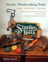
by Walter H. Jacob
Publisher: Early American Industries Assn.
Pub. Date: October 2011
ISBN-13: 978-0943196008
The Handplane Book
by Garrett Hack
Publisher: Taunton Press
Pub. Date: September, 2003
ISBN-13: 978-1561587124
by Michael Dunbar
Publisher: Sterling Publishing
Pub. Date: December 1989
ISBN-13: 978-0806966700
Working with Handplanes
by Fine Woodworking Editors (Editor)
Publisher: Taunton Press
Pub. Date: February, 2005
ISBN-13: 978-1561587483
by Scott Wynn
Publisher: Fox Chapel Publishing
Pub. Date: November, 2010
ISBN-13: 978-1565234536

Handplane Essentials
by Christopher Schwarz (signed)
Publisher: Popular Woodworking Books
Pub. Date: August, 2010
ISBN-13: 978-1440302985

by Kerry Pierce
Publisher: Schiffer Publishing, Ltd.
Pub. Date: February, 2011
ISBN-13: 978-0764335587

Handsaw Essentials
by Christopher Schwarz
Publisher: Betterway Books
Pub. Date: January, 2014
ISBN-13: 978-1440334337

by Christopher Schwarz (signed)
Publisher: Lost Art Press
Pub. Date: 2010
ISBN-13: 978-0578084138
Virtuoso - The Tool Cabinet and Workbench of Henry O. Studley
by Donald Williams, Narayan Nayar
Publisher: Lost Art Press
Pub. Date: May, 2015
ISBN-13: 978-0990623045
by William Fairham
Publisher: Toolemera Press
Pub. Date: 2010
ISBN-13: 978-0982532997
The Art of Joinery, Revised Edition ca. 1678
by Joseph Moxon
Commentary: Christopher Schwarz (signed)
Publisher: Lost Art Press
Pub. Date: 2013
ISBN-13: 978-0985077778
by Christopher Schwarz (signed)
Publisher: Lost Art Press
Pub. Date: 2022
ISBN-13: 978-1954697119

The Perfect Edge: The Ultimate Guide to Sharpening for Woodworkers
by Ron Hock (signed)
Publisher: Popular Woodworking Books
Pub. Date: January, 2010
ISBN-13: 978-1558708587
by Leonard Lee
Publisher: Taunton Press
Pub. Date: October, 1995
ISBN-13: 978-1561581252
↑